Now that we've nailed down the moment of inertia using two different methods, it's time to verify the jet force as accurately as possible. And we don't just need a single number; we need to characterize the jet force as a function of gas pressure supplied to the 3D-printed nozzles. The pendulum-based method we're using now gives a way to double-check the force/pressure relationship measured earlier by the force-sensitive resistor pads on the static test fire stand. The pads were difficult to calibrate and I suspected the data was pretty sloppy.
First we need to make a quick conversion of the trifilar pendulum apparatus. The pendulum only oscillates back and forth; it cannot rotate through large angles, and it certainly can't spin around completely. In the test firing we're about to do, the HAPP needs to rotate freely with minimal resistance.
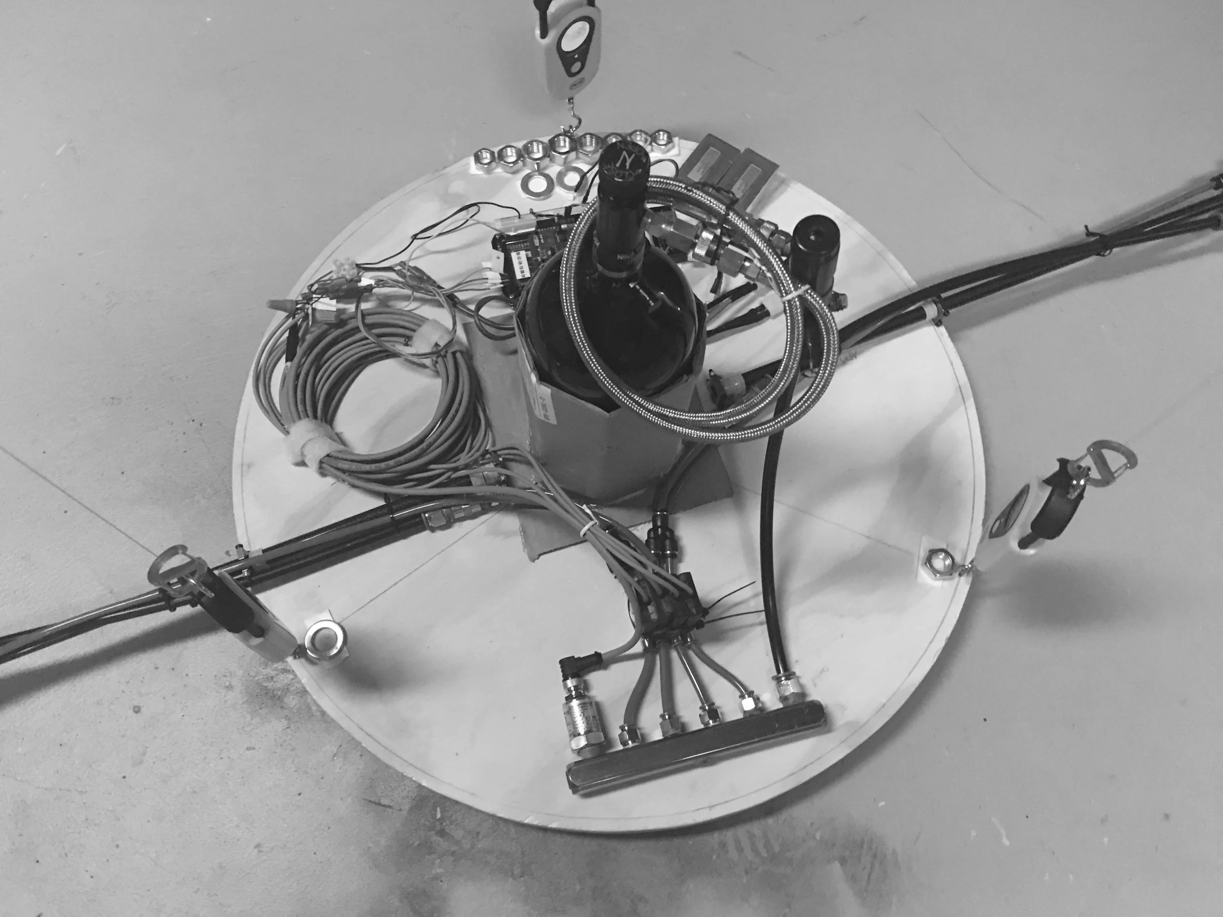
I replaced the pendulum's three perpendicular suspension lines with a 3-stranded bundle of 20-pound braided monofilament hung from the center of the pendulum support. The entire weight of the test rig can hang from this single bundle and spin quite easily. However, the test platform also needs to stay level, so I used three single monofilament lines to create a hanging basket "tripod" that attaches to the end of the central bundle. I also kept the digital scales in-line to provide continuing validation that the rig is properly balanced.
Ready to spin
Next I programmed the on-board Arduino to fire the jets for a short interval (350 milliseconds) and measure (1) the angular acceleration using the IMU chipset; and (2) the manifold pressure using the pressure transducer. Knowing acceleration and the moment of inertia, we can back-solve for jet force using Newton's Second Law for rotations (or Euler's equation if you prefer). Knowing the instantaneous pressure, we can also quantify the relationship between pressure and force.
Results:
As expected, the results were much more robust than those from the force-sensitive resistor. Although we saw some instantaneous force pad readings over 8 newtons, after a careful (3rd-degree polynomial) curve fit, the true pressure / force relationship measured by the pads is shown by the red line below. According to the jet nozzle math - thank you, thermodynamics - the relationship should be almost linear. Clearly, the force pads exhibit a pronounced non-linearity, despite my best attempts to calibrate around the non-linear response.
The black and grey lines, on the other hand, show the pressure / force relationship from our new and improved method based on measurement of the moment of inertia. I think this is some impressively clean data given that we're basically dealing with a lab apparatus made of plywood and fishing line!
The black line is for the nozzles v6 A&B, where A&B denote two copies of the same design. The design intent for v6 was 11N thrust at 100 PSI. AT 100 PSI we're seeing 8.04N thrust, which is 73% of design intent.
The grey line is for the nozzles v3 A&B. The design intent for v3 was 7.5N thrust at 100 PSI. At 100 PSI we're seeing 4.12N thrust, which is 55% of design intent.